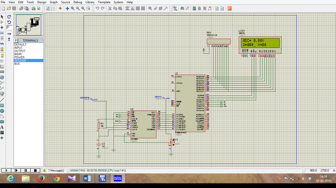
INTERFACING OF MICRO-CONTROLLER 8051 TO ADC (ADC 0804)
Micro-controller 8051 does
not has in-built ADC. So, we are using external ADC 0804. It is an 8-bit ADC so,
resolution = 8-bit.
ADC 0804 Pin Details:

DB7 - DB0 – Are 8 Data Pin
which hold Converted Digital data.
CS - It is an
Active low signal usually we can ground it, or use a pin from microcontroller
to control it by passing high to low pulse in the pin.
RD – It is
an Active low signal it use to read data from ADC0804 Data line (DB7-DB0).
WR - It is an Active low signal. When low to high signal is
passed in that pin the adc conversion start.
INTR - It is an Active low signal. It is used to Check for End
of Conversion.
Vref/2 – It is the References voltage is given to ADC for Step sizes Calculation of conversion.
AGND – Analog Ground.
DGND – Digital Ground.
Important Note:
Resolution of this ADC is
8bit, so that means the Steps ranges from (0-255)
Formula:
Step sizes = Vref/(2n -1); n = 8(Resolution of ADC).
= Vref/(256 - 1);
= Vref/255;
- To convert and display the data into LCD we use a formula to convert it to ascii.
if data =
125
for unit place data the formula is
- (data%10) = 5 => now or with 30h we get ascii value i.e.( 5|0x30 ) = 35
35 in ascii
means 5 numeric.
for tenth place data the formula is
- ((data/10)%10) = 2 => now or with 30h we get ascii value i.e.( 2|0x30 ) = 32
32 in ascii
means 2 numeric.
for
send data the formula is
- ((data/100)%10) = 1 => now or with 30h we get ascii value i.e.( 1|0x30 ) = 31
31 in ascii
means 1 numeric.
- To convert the data into LCD in Hex format using lookup table
- first Mask the low bits using 0xF0 and shift higher 4bit data to lower 4 bit and get the equal data from lookup table.
- then, mask the Higher bits using 0x0F and compare it with lookup table and display it.
Ex:
Higher bits = (data &
0xF0)>>4;
Lower bits = (data & 0x0F);

- To Convert the Digital data to analog we have formula ie;
Dout = Vin/step sizes;
So, when we alter it we get
Vin = Dout * Step size;
Vin = Dout * (Vref/2n-1);
Apply this formula we get input voltage;
Thus we have done the Coding for Interfacing of ADC to 8051.
Program for ADC:click for code
Video on above Example: Click for videos
Program for ADC:click for code
Video on above Example: Click for videos
sir actually i have a doubt ..could u pls tel wat exactly happens with v4 in CONVERTER ANALOG I/P
ReplyDelete