Showing posts with label Interfacing of ADC 0804. Show all posts

Wednesday, April 2, 2014

INTERFACING OF LCD IN 4-BIT MODE USING MICROCONTROLLER


INTERFACING OF LCD IN 4-BIT MODE USING MICRO-CONTROLLER

In this method of Interfacing LCD to Microcontroller using 4-bit mode is to reduce the usage of pin.

Mostly the Circuit having multiple function uses this method.

In this method PORT0 of UC is connected to LCD as Follows:

P0.0 => rs;    Register select Pin
P0.1 => en;  Enable Pin
P0.4 => D4;  data line
P0.5 => D5;         “
P0.6 => D6;         “
P0.7 => D7;         “

In method we use same port for control pin as well as data line. So each data is send by breaking it into two 4bit part.

To initialize LCD in this method a command used is 0x28

Which means 16 x 2 LCD in 4-bit mode.

Before doing that we should send a sequence of 0x30, 0x30, and 0x20.

To send this we use only cmd_hf function which send only 3, 3, and 2 as sequence to LCD to enable in 4-Bit mode.

To send each data we should first clear the higher order bit i.e. from P0.4 – P0.7

And masking the input is properly shown in video.

  • We should mask Higher bit and rest all bit are clear.
  •  We send by latching.
  • We should now mask lower bit and send to UC.


This is how a 4-Bit mode LCD works.
Thank you for reading.
Plz Do share and Subscribe.

Source Code: click for code
For Videos on this Example: Click on the link


Monday, March 3, 2014

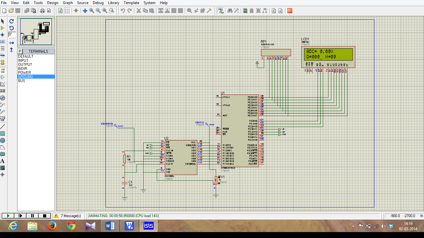
INTERFACING OF MICRO-CONTROLLER 8051 TO ADC (ADC 0804)

 INTERFACING OF MICRO-CONTROLLER 8051 TO ADC (ADC 0804)

Micro-controller 8051 does not has in-built ADC. So, we are using external ADC 0804. It is an 8-bit ADC so, resolution = 8-bit.

ADC 0804 Pin Details:


DB7 - DB0 – Are 8 Data Pin which hold Converted Digital data.

CS - It is an Active low signal usually we can ground it, or use a pin from microcontroller to control it by passing high to low pulse in the pin.

RD – It is an Active low signal it use to read data from ADC0804 Data line (DB7-DB0).

WR - It is an Active low signal. When low to high signal is passed in that pin the adc conversion start.

INTR - It is an Active low signal. It is used to Check for End of Conversion.

Vref/2 – It is the References voltage is given to ADC for Step sizes Calculation of conversion.

AGND – Analog Ground.


DGND – Digital Ground.

Important Note:

Resolution of this ADC is 8bit, so that means the Steps ranges from (0-255)

Formula:
            Step sizes = Vref/(2n -1);              n = 8(Resolution of ADC).
                            = Vref/(256 - 1);
                                   =  Vref/255;  


  • To convert and display the data into LCD we use a formula to convert it to ascii.

                                      if data = 125  
     for unit place data the formula is

  •         (data%10) = 5 => now or with 30h we get ascii value i.e.( 5|0x30 ) = 35

                               35 in ascii means 5 numeric.

     for tenth place data the formula is

  •          ((data/10)%10) = 2 => now or with 30h we get ascii value i.e.( 2|0x30 ) = 32

                               32 in ascii means 2 numeric.

     for send data the formula is

  •        ((data/100)%10) = 1 => now or with 30h we get ascii value i.e.( 1|0x30 ) = 31

                               31 in ascii means 1 numeric.

  • To convert the data into LCD in Hex format using lookup table
  •  first Mask the low bits using 0xF0 and shift higher 4bit data to lower 4 bit and        get the equal data from lookup table.
  •  then, mask the Higher bits using 0x0F and compare it with lookup table and          display it.

                 Ex:
              Higher bits = (data & 0xF0)>>4;
              Lower bits = (data & 0x0F);


  • To Convert the Digital data to analog we have formula ie;

                       
                        Dout = Vin/step sizes;
                        So, when we alter it we get
                        Vin = Dout * Step size;
                        Vin = Dout * (Vref/2n-1);

Apply this formula we get input voltage;

Thus we have done the Coding for Interfacing of ADC to 8051. 


Program for ADC:click for code

Video on above Example: Click for videos